

Hydropower Plant Cooling & Automatic Cleaning Systems
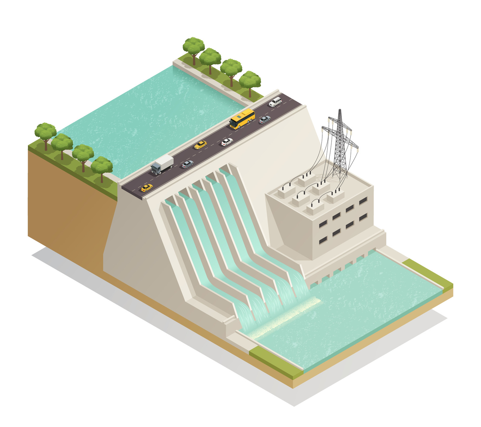
Hydropower cooling systems operate continuously under difficult surface-water conditions. Over time, fouling inside turbine oil coolers and heat exchangers becomes unavoidable.
Traditional maintenance requires shutdowns, manual cleaning, and disassembly of critical cooling equipment. EQOBRUSH automatically removes fresh fouling during operation using periodic flow reversal and brush cleaning technology. Click left to watch video.
Proven technology. Live operation. Installed in some of Asia’s largest hydroelectric facilities.

HYDROPOWER PLANTS: THE BACKBONE OF THE RENEWABLE GRID
As the world’s largest source of renewable electricity, hydropower supplies over 17% of global power generation — and its strategic importance is growing.
Unlike wind and solar, hydropower is dispatchable: operators control output in real time by regulating water flow, making it the only major renewable source that can respond on demand to grid requirements.
As grids worldwide absorb increasing shares of intermittent renewables, this controllability makes hydropower the backbone of a stable, decarbonised energy system — and drives continued investment in new capacity and the optimisation of existing plants.
For hydropower operators, this responsibility cuts both ways: an unexpected unit shutdown caused by fouling-related overheating is not just a maintenance problem — it is a grid reliability event.

COOLING REQUIREMENTS IN HYDROPOWER PLANTS

The following components in Hydro power generation require cooling:
- Hydro Generators
- Bearings
- Transformers
- Speed governors
- Turbine shaft axial seals
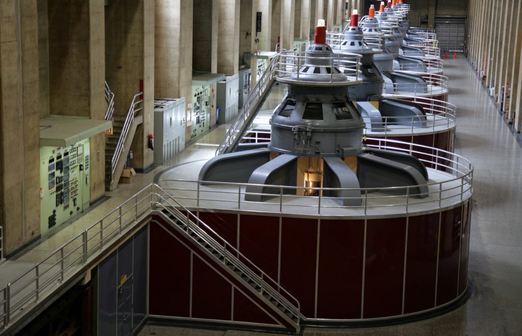
Electricity generation in the hydro-generator that is powered by the turbine releases heat that needs to be removed to be able to keep running at optimum capacity. The generators can be air-cooled or water- cooled.
CHALLENGES IN HYDROPOWER PLANT COOLING
Surface water as a cooling medium leads to severe fouling issues
The cooling is realized by a closed system that circulates the cooling medium (water or oil) over the components and a heat exchanger where it releases the heat to secondary cooling water. The secondary cooling water is the same surface water that drives the turbines and it causes problems with fouling/scaling of those heat exchangers. As a result of this, the turbines need to be shut down regularly for heat exchangers to be cleaned. The economic impact due to loss of income for each day of turbine downtime is enormous, in addition to the budget that needs to be set aside for the workload of this.
WHY OIL COOLING IN HYDROPOWER PLANTS MATTERS

Hydro generators run on bearings — and bearings run on oil.
The thrust bearing alone carries the entire vertical load of the rotating shaft, the runner, and the water pressure acting on it: in a large Francis unit, that can exceed several thousand tonnes of axial force.
Without effective cooling, bearing oil temperatures climb, viscosity drops, and the lubricating film that separates metal surfaces breaks down. The result is accelerated wear, or in a worst case, a catastrophic bearing failure that takes a unit offline for months.
Oil-to-water heat exchangers are the critical link in this hydropower plant cooling chain — and they are directly exposed to the fouling risk that EQOBRUSH is designed to eliminate.
Cooling Challenges of Grid-Scale Energy Storage
Maximizing Reliability in Modern Hydropower Systems
The global transition toward renewable energy is redefining the role of hydropower, shifting its function from constant baseload supply to the dynamic “battery” of the power grid. With the rapid expansion of Pumped Storage Hydropower (PSH) projects and the integration of variable-speed technologies, modern installations are being pushed to their technical limits. Frequent switching and intensive peak-load operations have led to a significant increase in thermal stress on both generators and turbines.
In this high-stakes environment, the reliability of the cooling system—specifically the oil cooling for bearings and transformers—has become the critical factor for operational uptime. To maintain this vital infrastructure, it is essential to keep heat exchangers (HX) in pristine condition. Even minor biofilm accumulation or scaling can drastically reduce cooling efficiency, leading to unplanned downtime during crucial price peaks in the energy market.
Automatic tube cleaning is no longer a luxury; it is a necessary insurance policy for the continuity, safety, and efficiency of modern hydropower assets.
In this high-stakes environment, the reliability of the cooling system—specifically the oil cooling for bearings and transformers—has become the critical factor for operational uptime. To maintain this vital infrastructure, it is essential to keep heat exchangers (HX) in pristine condition. Even minor biofilm accumulation or scaling can drastically reduce cooling efficiency, leading to unplanned downtime during crucial price peaks in the energy market.
Automatic tube cleaning is no longer a luxury; it is a necessary insurance policy for the continuity, safety, and efficiency of modern hydropower assets.

THE ECONOMIC IMPACT OF CLEANING SHUTDOWN
The real cost of heat exchanger fouling in hydropower is a maintenance cost, not a production cost. Large multi-unit installations have redundancy built in — individual units rotate through maintenance schedules while others remain online. But the labour, logistics, and mechanical work of manually opening, cleaning, inspecting, and reassembling heat exchangers several times per year per unit adds up to a substantial and recurring budget line.
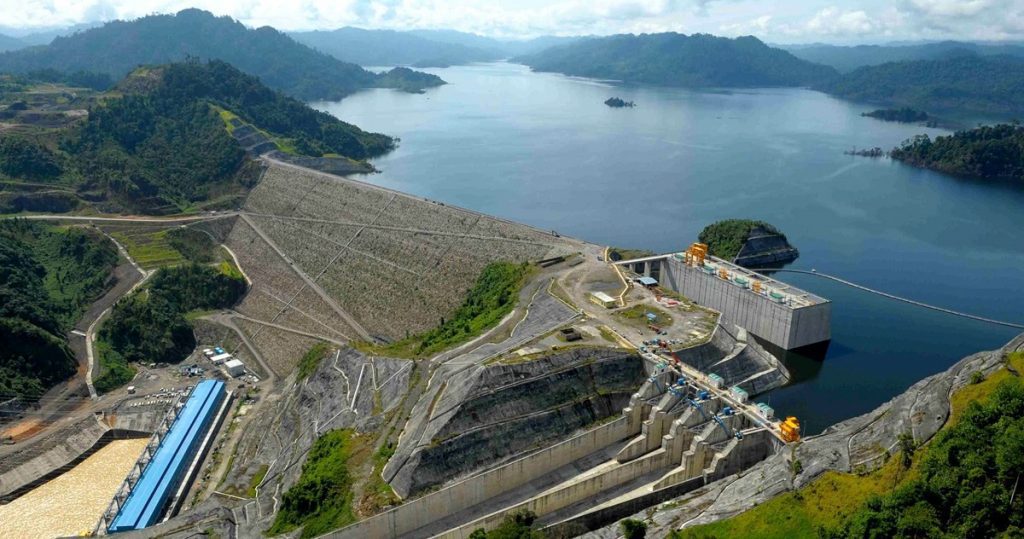
One of the clearest published examples comes from the Bakun Hydroelectric Plant in Sarawak, Malaysia — a 2,400 MW facility with 8 Francis turbine units, one of the largest hydroelectric installations in Southeast Asia. In their published performance report, Sarawak Energy documents the installation of an Automatic Tube Cleaning System operating on a 4-hour flow reversal interval across their heat exchangers. With the system installed on 6 of their 10 units, they report a proven cost saving of approximately RM 600,000 — attributed directly to the elimination of labour-intensive manual heat exchanger cleaning.
The Bakun Hydroelectric Plant in Sarawak, Malaysia uses EQOBRUSH hydropower plant cooling systems to reduce heat exchanger fouling and minimize maintenance-related downtime.
For smaller single-unit or run-of-river installations without full redundancy, the case is stronger still: fouling-related thermal issues can force a complete plant shutdown, making every hour of avoided downtime directly recoverable revenue.
Typical payback periods: 18 to 36 months, depending on installation size, water quality, and current cleaning frequency.
Automatic Tube Brushing for Hydropower Plant Cooling Systems - the most elegant solution

EQOBRUSH uses a flow reversal valve to automatically reverse the cooling water flow direction at set intervals — typically every 4 hours. This propels nylon brushes, stored in catch baskets at each tube end, through the heat exchanger tubes, continuously removing biofilm and particulate deposits before they can consolidate into scale.
Because fouling never gets the opportunity to harden, manual cleaning is eliminated entirely. Tube pitting corrosion — a common consequence of localised deposit formation — is also prevented, extending the service life of the heat exchanger itself.
Standard EQOBRUSH systems accommodate inlet/outlet pipe diameters up to 600mm. Larger installations can be served with engineered-to-order configurations.
EQOBRUSH systems in Hydro Power applications deliver:
- Elimination of manual heat exchanger cleaning
- Reduced maintenance labour and scheduling overhead
- Extended tube service life — pitting corrosion eliminated
- Predictable maintenance budget with no cleaning surprises
- Applicable to generators, bearings, transformers, speed governors, and shaft seal coolers
- Standard systems up to 600mm pipe diameter; larger configurations on request
Ready to eliminate heat exchanger maintenance from your plant’s schedule?